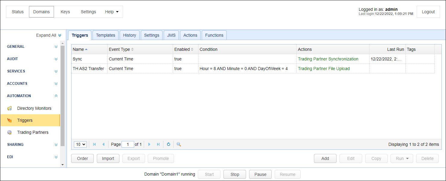
A trigger is a method of listening for events and responding with actions based on whether conditions are met. To view a list of triggers, click on the AUTOMATION > Triggers > Triggers tab for the desired domain.
Figure 34
Step 1
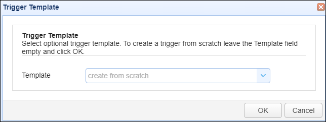
To add a trigger click on the Add button in the lower right corner. The first thing you'll see is the Trigger Template dialog. (See Using trigger templates) If you wish to proceed with the trigger creation process without using a template, just click OK without selecting any template from the Template drop-down list. On the other hand, if you wish to use a template, expand the Template drop-down list and select your desired template before clicking OK. If a template is selected, you'll be able to proceed with the trigger creation process but with the trigger already pre-populated with the values found in the template. You may change any setting as you see fit.
Figure 359
Next, the Add Trigger wizard will be displayed.
Figure 35
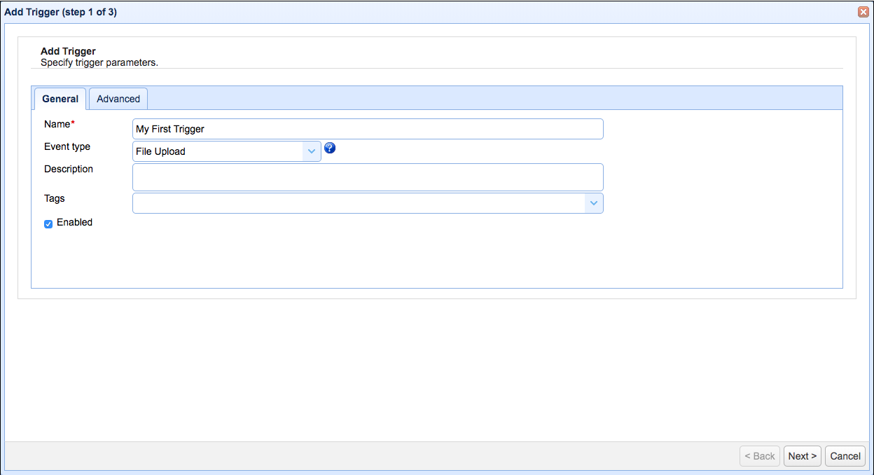
General
Name - A unique name identifying this trigger.
Event Type - The type of event you want to listen for.
Description - Description of this trigger.
Tags - If used, this trigger will only be visible to administrators with a system administrator flag or who have been assigned a role with specified tag.
Enabled - Enables/disables trigger.
Figure 280
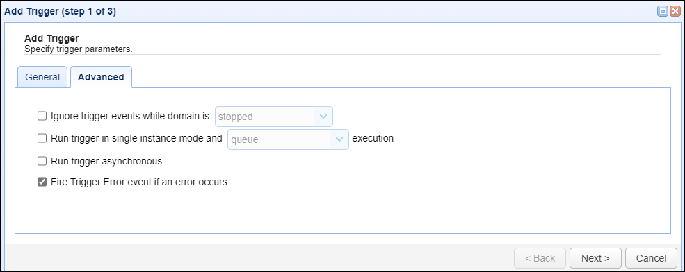
Advanced
Ignore trigger events while domain is - If checked, events will not be processed when domain is in specified state.
Run trigger in single instance mode - Specifies that only one instance of this trigger should be run at a time. If an instance of this trigger is already running, a second instance can be either queued or skipped. The exact behavior can be specified by choosing between queue and skip in the drop-down list.
Run trigger asynchronous - If checked, trigger will be processed asynchronously.
Fire Trigger Error event if error occurs - If an error occurs while executing any of the actions associated with this trigger, a Trigger Error event will be raised. You may capture this event using a trigger that listens for the Trigger Error event and respond appropriately.
Click the Next button to proceed to the next screen and to specify trigger conditions, if any.
Step 2
Trigger conditions can be entered either manually (enable "Override") or by using the GUI-based Expression Builder. If you develop an expression using the Expression Builder, the expression will be automatically written to the Expression box. This box will be read-only if the Override checkbox is unchecked. Should you wish to write the expression manually yourself, check the Override checkbox. Once the Override button is checked, the Expression Builder will be disabled.
Figure 36
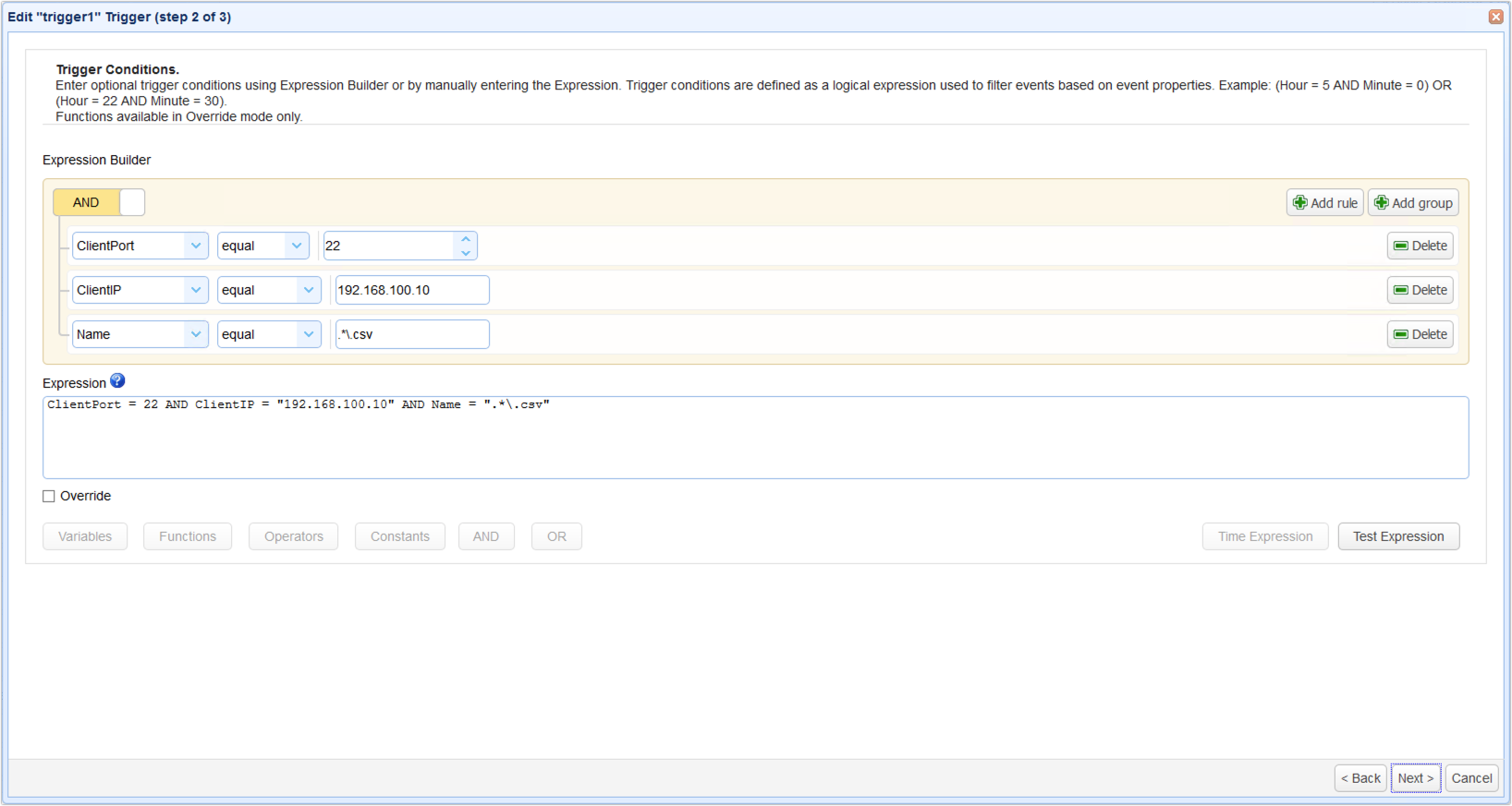
Expression - Enter a trigger condition (if any) in this text field. (See Writing conditions)
Override - Enable the checkbox if you wish to enter the trigger condition directly into the Expression box.
Test Expression - Click this button to test your trigger condition. (See Testing conditions)
Note: The following buttons will only be enabled if the Override checkbox is checked.
Variables - Click this button to display a list of supported variables. This list will vary depending on the Event type used in the previous screen.
Functions - Click this button to display a list of functions. (See Function types)
Operators - Click this button for a list of supported Operators (e.g. =, !=, <, >, etc.). Hover your mouse over an operator to see a context-sensitive help.
Constants - Click this button for a list of supported constants.
AND - Click this button to insert the AND logical operator
OR - Click this button to insert the OR logical operator
Time Expression - Click this button for a more convenient way of specifying time expression parameters. (See Using time based triggers).
Click the Next button to proceed to the next screen and to add one or more trigger actions.
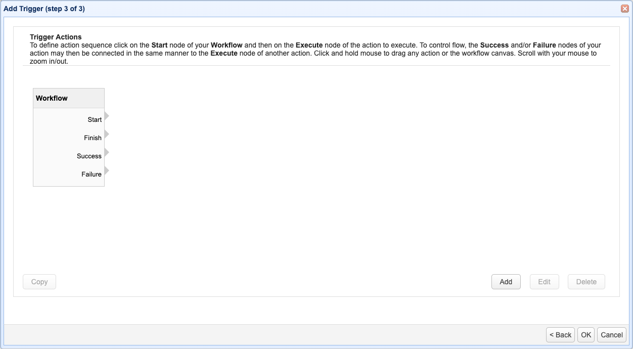
Step 3
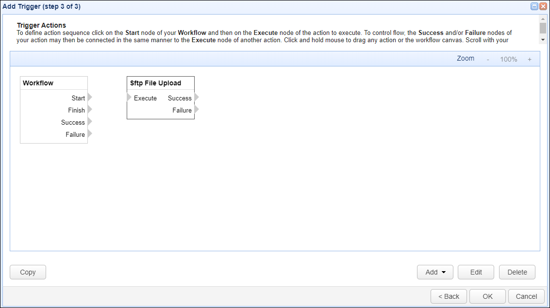
Trigger actions are added as nodes in a flowchart. When the Trigger Actions window first appears, you'll see a canvas area with a single node named Workflow, as depicted in Figure 37 below. The Workflow node has four outputs, Start, Finish, Success and Failure. Each of the four Workflow outputs support the creation of multiple trigger actions, meaning you can have one or more actions linked to the Start output and one or more actions linked to the Finish output, etc. You can then have one or more actions linked to the output of a prior action's Success and one or more actions linked to a prior action's Failure. When there is more than one action linked to the same output (e.g. two actions linked to the Start of the Workflow, or three actions linked to the Success of a prior action), the multiple actions are executed asynchronously (concurrently). Please note that for most trigger actions the input name is Execute, and the output names are Success and Failure. There are some actions where the input and output names are different. For example, the If action input name depends on the Condition field entered by the user. The output names are Then and Else. For all actions, the input name is on the left-hand side of the node, and the output names are on the right-hand side.
Workflow outputs
Start - Used to define what trigger action(s) to execute when the trigger execution begins.
Finish - Used to define what trigger action(s) to execute when the trigger execution ends.
Success - Used to define what trigger action(s) to execute if all actions complete successfully in the Start or Finish workflows.
Failure - Used to define what trigger action(s) to execute if any action fails execution in the Start or Finish workflows.
Add, Edit, Delete, Copy, Reset Zoom Level
Add - This button allows you to add a trigger action. When selecting this option, an Add Action window will pop up. Another way to add an action is to right-click on a Workflow node, action node, or in the white space of the canvas area. The Add option will appear in a pop-up menu, where you can then expand the Add sub-menu to see the options, then select Add action.Note: In the Add sub-menu options you will also be able to select Add condition and Add cycle. Add condition allows you to quickly add an If action without having to select it from the drop-down list of actions. Similarly, the Add cycle menu options allows you to quickly add a ForEach trigger action without having to select it from the drop-down list of actions.
Edit - Select an existing trigger action, then click on this button to edit it. You can also right-click on a trigger action, then select Edit from the pop-up menu. As a final way to edit an action, you can double-click on the desired action node, which will pull the action up in the Edit <name> Action window.
Delete - Select an existing trigger action and then click this button to delete it. You can also mouse over an action node you wish to delete, which will result in a red "x" appearing in the node's right-hand corner. Click the x to delete the trigger action. A final way to delete an existing trigger action is to right-click on the action, then select Delete from the pop-up menu. Using either method, you will be prompted to confirm the deletion.
Copy - Select an existing trigger action, then click this button to copy it. You can also mouse over an action you wish to copy, which will result in a copy icon appearing to the right of the trigger action's name. Click the copy icon to copy the trigger action. A final way to copy an existing trigger action is to right-click on the action, then select Copy from the pop-up menu.
Reset Zoom Level - This is a menu option that you will see when you right-click in the white space of the canvas area, or you right-click on any node or link. If you have increased or decreased the zoom level, selecting this option will display the nodes and links in the canvas area at 100%.
Figure 37
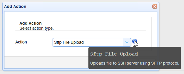
To add a trigger action, click the Add button, or use any other method previously described. Expand the Action drop-down list to view all available trigger actions. To see a context help for a particular trigger action, select the action from the drop-down list and click the adjacent question mark icon (See Figure 281). Select the action you want to use.
Figure 281
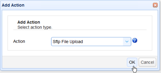
Click the OK button to proceed to the action parameters screen.
Figure 282
The contents of this screen will vary depending on the selected trigger action. Enter pertinent details for the action in question and then click OK.
Figure 283
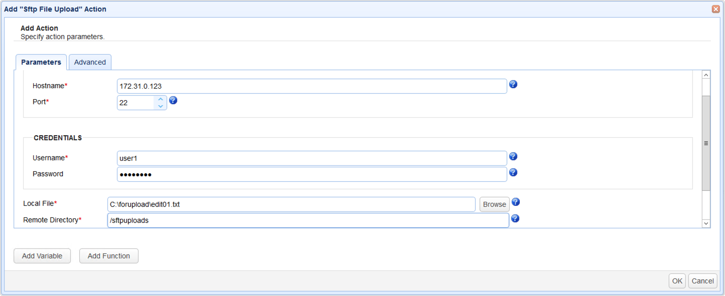
A new trigger action node bearing the action type chosen (e.g. Sftp File Upload) will then be added to the canvas. Most trigger actions have one input, Execute, and two outputs, Success and Failure (as mentioned earlier, there are a couple of actions where the input/output names are different). You may link the Sftp File Upload action to either the Start or Finish outputs of the Workflow node. If you link this action to the Start output, this action will be executed as soon as the trigger begins execution. If you link it to the Finish output, it will execute once the trigger execution completes.
As you create new action nodes, they will be placed in a default location on the canvas area. You can move the Workflow node or any action node around by clicking on the title bar of the node, then moving (dragging) it to your desired location. There is a feature that when enabled (it is disabled by default), will organize your actions by snapping them to the canvas area grid. This means that the action nodes will be placed at the closest intersection on the grid (grid lines are not visible on the canvas area and cannot be made visible). If you wish to use this feature, right-click anywhere in the canvas area (including on the nodes and links) which will pull up a pop-up menu where the Align actions to grid menu option can be selected. When selected:
| • | The existing nodes and any future nodes you create in the current session will automatically align in the canvas area. |
| • | A green check will appear to the left of the Align actions to grid menu option (it serves as a visual aid for you to know this feature is enabled). |
When Align actions to grid is enabled, existing and new nodes will be snapped to the grid which means you do not have granular control of where the nodes are placed on the canvas area. The system will align them in the grid for you. You can still manually move the nodes around as previously described, however, they will be snapped into the nearest grid location as determined by the system. Check the Align actions to grid menu option to disable this feature (the green check is removed from the menu option when disabled). Once disabled, you can manually move the nodes in a precise desired location, and they will remain where you place them.
When you save the trigger, the system saves the node layout, therefore when you edit the trigger in the future, the nodes will be in the position they were in when you last saved it. This is true regardless of whether Align actions to grid is enabled or disabled when you save the trigger.
Figure 293
To link an action node to the Workflow's Start output, you can use the original method, or the new method.
Original method
1) Click on the Workflow's Start label or click on the output connector symbol (a "half diamond") to the right of the Start label.
2) Release your mouse (do not hold down any mouse button).
3) Move the mouse to the desired action's input that you wish to link up to. As you move your mouse, a dashed line will appear. The action's input is always on the left-hand side of the action node, and is most frequently named Execute, but there are a few exceptions (an exception example is provided in the first paragraph under the "Step 3" heading above).
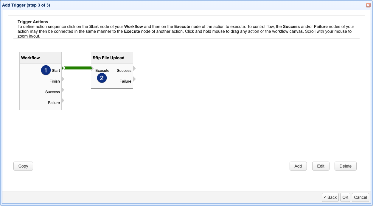
4) Click the mouse when you see the target action node's input connector symbol (a "half diamond") turn a different shade of color, indicating it is active. A link will be generated. You will know the link is successful when you see a green arrow pointing from Start on the Workflow to the input connector symbol on the target action node. This is depicted in Figure 294.
New method
1) Click on the Workflow's Start label or click on the output connector symbol (a "half diamond") to the right of the Start label. Do not release the mouse. Continue to step 2.
2) Drag the mouse to the desired action's input that you wish to link up to. As you move your mouse, a dashed line will appear. The action's input is always on the left-hand side of the action node, and is most frequently named Execute, but there are a few exceptions.
3) Release the mouse when you see the target action node's input connector symbol (a "half diamond") turn a different shade of color, indicating it is active. A link will be generated. You will know the link is successful when you see a green arrow pointing from Start on the Workflow to the input connector symbol on the target action node. This is depicted in Figure 294.
Note: All trigger actions must be linked to an output. If there is no link to action(s) when you save the trigger, a message box will pop up stating "Orphan actions detected will not be saved. Are you sure you wish to continue?". Make sure to include a link before saving, or the action will not be saved.
Figure 294
Adding more action nodes
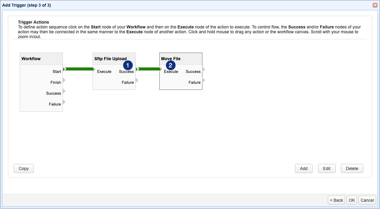
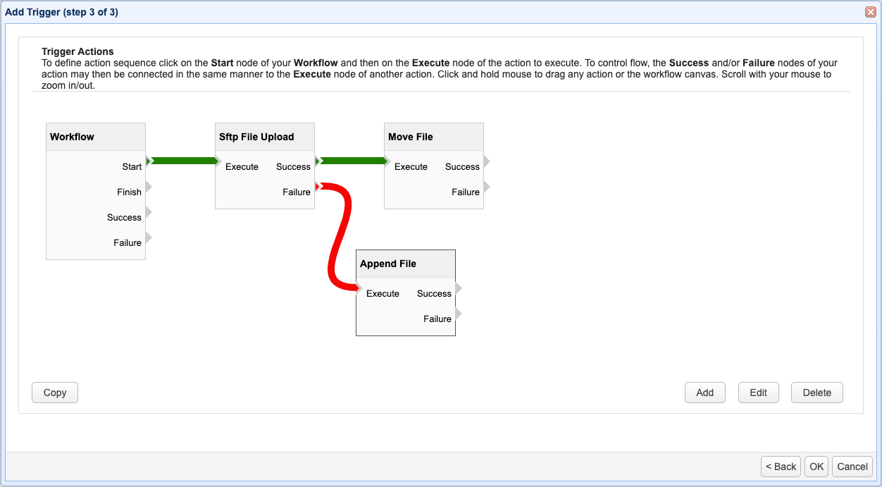
Should you wish to execute another trigger action after an existing action, just add another action node and link it to the previous node by clicking on 1) either the Success or Failure outputs of the first node and then 2) on the Execute input of the second node. You may add more nodes as you wish and then link them in a daisy-chain fashion. To change the order of execution of existing action nodes, just delete all affected links (by selecting the link and clicking the Delete button,or by right-clicking and selecting Delete from the pop-up menu) and then reattach new links that reflect the desired order of execution. You may also rearrange the nodes if you wish, as previously described. In the figure depicted below, when the trigger event occurs, the workflow will start by running the Sftp File Upload action. If that action is successful, the Move File action will execute.
Figure 295
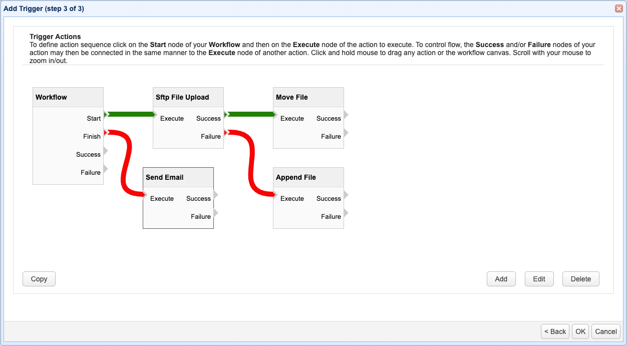
In most cases, you would link a succeeding action node to the Success output of a previous action node. However, action nodes can also be linked via the Failure output. Normally, this is done for error handling purposes. For example, if an action fails, you might want MFT Server to send an email to a designated server admin (e.g. via the Send Email action) or log the failure to a file (e.g. via the Append File action), or perhaps do both. Performing both Failure actions, Append File and Send Email, is what is depicted in Figure 296 below. Whenever you have two or more actions linked to an output (in this case Failure), the actions (should a failure occur) will run asynchronously. As discussed in the Trigger lifecycle section, you can assign more than one action to any single output, which also includes the Workflow outputs.
Figure 296
Finishing a trigger
You may link one or more action nodes the Workflow's Finish output. This action will be executed regardless whether or not all actions linked to Start are able to execute successfully.
Figure 297
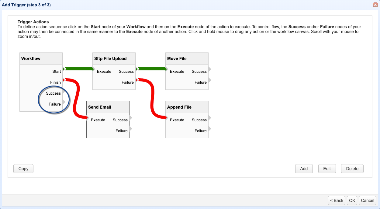
Trigger Success and Failure
The Success and Failure outputs of the Workflow node allow you to specify global success/failure workflows for the entire trigger. For example, if any trigger action fails, action(s) in the Workflow node's Failure output will execute. On the other hand, if all actions execute successfully, action(s) in the Workflow node's Success output will execute.
If an action in the Workflow node's Failure or Success output fails execution, then the Trigger Error event will be raised as normal. If this happens, the action(s) in the Workflow node's Failure output will not be executed again. This is to prevent an infinite loop.
When rerunning a trigger via the Rerun button in the AUTOMATION > Triggers > History tab, it's possible for there to be multiple points of failure; e.g. a failure in one of the Workflow > Start actions + a failure in one of the Workflow > Finish actions. When rerunning a trigger using the 'Rerun from point of failure' option, make sure that you always run from the first point of failure.
Figure 349
See also